Toggle navigation
首页
问答
文章
积分商城
专家
专区
更多专区...
文档中心
返回主站
搜索
提问
会员
中心
登录
注册
OLED显示屏
SPI
【RTduino】RTduino SPI屏幕驱动开发参考案例
发布于 2023-06-16 09:37:46 浏览:577
订阅该版
[tocm] # RTduino SPI屏幕驱动开发案例 ## 硬件平台 * [STM32L475潘多拉开发板](https://github.com/RT-Thread/rt-thread/tree/master/bsp/stm32/stm32l475-atk-pandora) * [SSD1306 SPI显示屏](https://spin.atomicobject.com/2017/10/14/add-oled-particle-device/) ## 软件平台 * [stm32l475-atk-pandora BSP](https://github.com/RT-Thread/rt-thread/tree/master/bsp/stm32/stm32l475-atk-pandora) * [env-windows](https://github.com/RT-Thread/env-windows) * [STM32CubeProgrammer](https://www.st.com/en/development-tools/stm32cubeprog.html#get-software) * [VScode](https://code.visualstudio.com/download) ## 下载RTduino库 Step1:首先下载[官方RT-Thread主仓库](https://github.com/RT-Thread/rt-thread) ```bash git clone https://github.com/RT-Thread/rt-thread.git ``` Step2:进入潘多拉所在的bsp目录(`.\rt-thread\bsp\stm32\stm32l475-atk-pandora`),打开ENV工具打开 menuconfig 菜单 ```bash menuconfig ``` Step3:进入以下目录:` → Hardware Drivers Config → Onboard Peripheral Drivers → Compatible with Arduino Ecosystem (RTduino)`,使能 RTduino 库 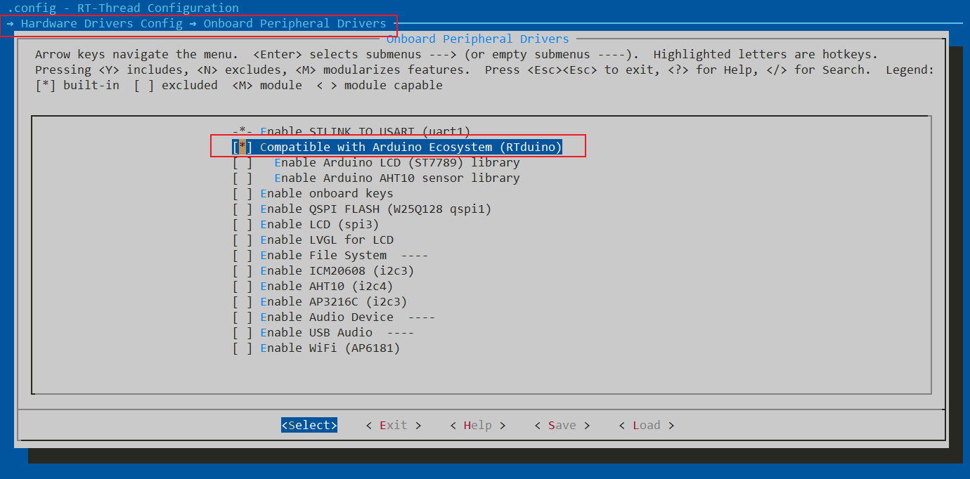 ## 使能Adafruit SSD1306软件包 Step1:进入如下路径:` → RT-Thread online packages → Arduino libraries → Display → Adafruit SSD1306: SSD1306 monochrome 128x64 and 128x32 OLEDs driver` 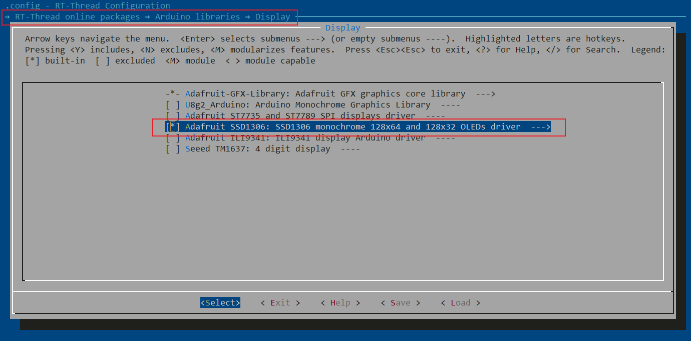 Step2:完成上述操作后,退出ENV并更新软件包命令进行软件包下载 ```bash pkgs --update ``` ## 添加测试程序 我们回到BSP目录下,在以下路径找到测试程序:`.\rt-thread\bsp\stm32\stm32l475-atk-pandora\packages\Adafruit-SSD1306-latest\examples\ssd1306_128x64_spi\ssd1306_128x64_spi.ino` 其实这个文件就是Arduino的应用程序,选择Arduino或Vscode或记事本打开都可以,复制示例代码到`arduino_main.cpp文件中(D:\Desktop\rt-thread\bsp\stm32\stm32l475-atk-pandora\applications\arduino_main.cpp)` 将`arduino_main.cpp`中的代码全部替换,**注意:需要保留 `#include <Arduino.h>` 头文件,这块一定要注意** 这里有个注意事项需要留意:SSD1306 SPI屏引脚映射表如下: | 引脚描述 | OLED硬件接口 | STM32引脚编号 | RTduino引脚编号 | | :----------: | :------: | :-----------: | :-------------: | | SPI Clock | D0 | PB13 | 29 (D29) | | SPI MOSI | D1 | PB15 | 31 (D31) | | Data/Command | DC | PB9 | 2 (D2) | | Chip Select | CS | PB12 | 8 (D8) | | Reset | RES | PD14 | 5 (D5) | > 注:D0、D1为RTduino SPI引脚;DC、CS、RES为通用GPIO 修改`arduino_main.cpp`文件中的SPI引脚,参考上面的引脚映射表 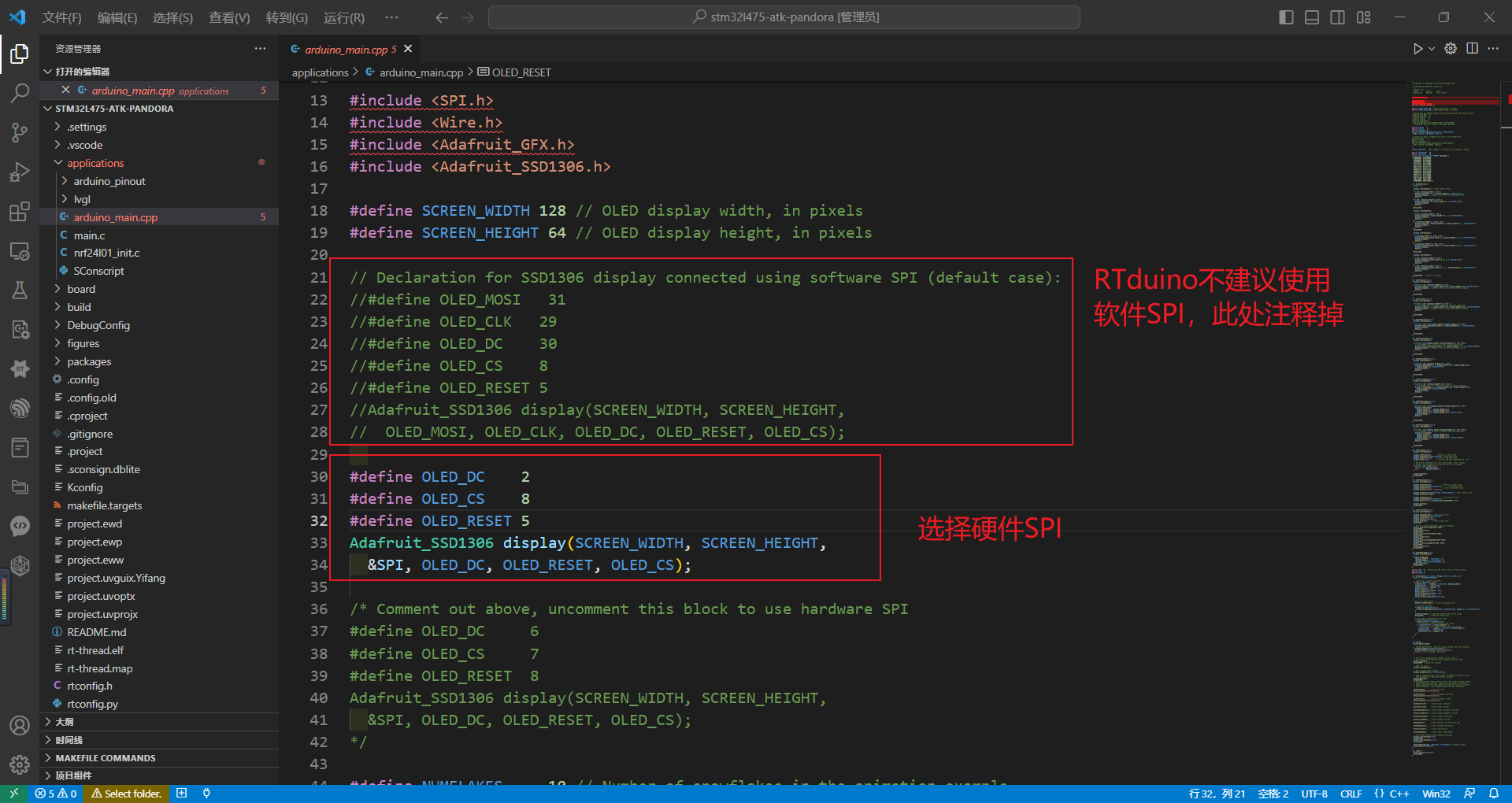 然后我们根据上述信息进行硬件接线,潘多拉开发板参考下面这张图: 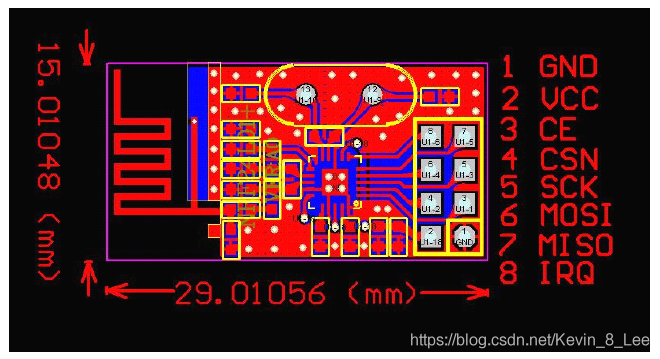 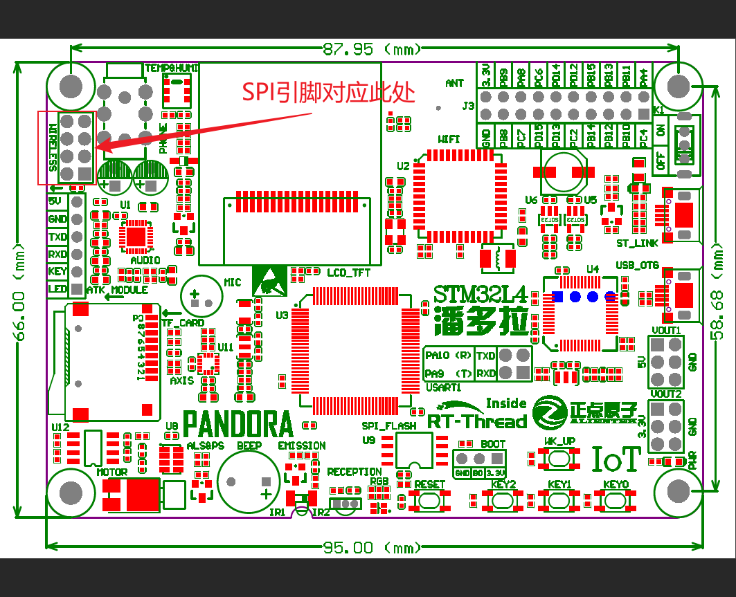 ## 编译 Step1:先不着急编译,由于 Adafruit 这块的函数命名并不规范,在GCC编译下会发生报错,需要我们**将void setup()函数中用户自定义的函数进行函数声明,或直接把函数移动到void setup()函数之前** 下面是完整的`arduino_main.cpp`函数 ```cpp /* * Copyright (c) 2006-2022, RT-Thread Development Team * * SPDX-License-Identifier: Apache-2.0 * * Change Logs: * Date Author Notes * 2021-12-10 Meco Man first version */ #include <Arduino.h> #include <SPI.h> #include <Wire.h> #include <Adafruit_GFX.h> #include <Adafruit_SSD1306.h> #define SCREEN_WIDTH 128 // OLED display width, in pixels #define SCREEN_HEIGHT 64 // OLED display height, in pixels // Declaration for SSD1306 display connected using software SPI (default case): //#define OLED_MOSI 31 //#define OLED_CLK 29 //#define OLED_DC 30 //#define OLED_CS 8 //#define OLED_RESET 5 //Adafruit_SSD1306 display(SCREEN_WIDTH, SCREEN_HEIGHT, // OLED_MOSI, OLED_CLK, OLED_DC, OLED_RESET, OLED_CS); #define OLED_DC 2 #define OLED_CS 8 #define OLED_RESET 5 Adafruit_SSD1306 display(SCREEN_WIDTH, SCREEN_HEIGHT, &SPI, OLED_DC, OLED_RESET, OLED_CS); /* Comment out above, uncomment this block to use hardware SPI #define OLED_DC 6 #define OLED_CS 7 #define OLED_RESET 8 Adafruit_SSD1306 display(SCREEN_WIDTH, SCREEN_HEIGHT, &SPI, OLED_DC, OLED_RESET, OLED_CS); */ #define NUMFLAKES 10 // Number of snowflakes in the animation example #define LOGO_HEIGHT 16 #define LOGO_WIDTH 16 static const unsigned char PROGMEM logo_bmp[] = { 0b00000000, 0b11000000, 0b00000001, 0b11000000, 0b00000001, 0b11000000, 0b00000011, 0b11100000, 0b11110011, 0b11100000, 0b11111110, 0b11111000, 0b01111110, 0b11111111, 0b00110011, 0b10011111, 0b00011111, 0b11111100, 0b00001101, 0b01110000, 0b00011011, 0b10100000, 0b00111111, 0b11100000, 0b00111111, 0b11110000, 0b01111100, 0b11110000, 0b01110000, 0b01110000, 0b00000000, 0b00110000 }; void testdrawline() { int16_t i; display.clearDisplay(); // Clear display buffer for(i=0; i<display.width(); i+=4) { display.drawLine(0, 0, i, display.height()-1, SSD1306_WHITE); display.display(); // Update screen with each newly-drawn line delay(1); } for(i=0; i<display.height(); i+=4) { display.drawLine(0, 0, display.width()-1, i, SSD1306_WHITE); display.display(); delay(1); } delay(250); display.clearDisplay(); for(i=0; i<display.width(); i+=4) { display.drawLine(0, display.height()-1, i, 0, SSD1306_WHITE); display.display(); delay(1); } for(i=display.height()-1; i>=0; i-=4) { display.drawLine(0, display.height()-1, display.width()-1, i, SSD1306_WHITE); display.display(); delay(1); } delay(250); display.clearDisplay(); for(i=display.width()-1; i>=0; i-=4) { display.drawLine(display.width()-1, display.height()-1, i, 0, SSD1306_WHITE); display.display(); delay(1); } for(i=display.height()-1; i>=0; i-=4) { display.drawLine(display.width()-1, display.height()-1, 0, i, SSD1306_WHITE); display.display(); delay(1); } delay(250); display.clearDisplay(); for(i=0; i<display.height(); i+=4) { display.drawLine(display.width()-1, 0, 0, i, SSD1306_WHITE); display.display(); delay(1); } for(i=0; i<display.width(); i+=4) { display.drawLine(display.width()-1, 0, i, display.height()-1, SSD1306_WHITE); display.display(); delay(1); } delay(2000); // Pause for 2 seconds } void testdrawrect(void) { display.clearDisplay(); for(int16_t i=0; i<display.height()/2; i+=2) { display.drawRect(i, i, display.width()-2*i, display.height()-2*i, SSD1306_WHITE); display.display(); // Update screen with each newly-drawn rectangle delay(1); } delay(2000); } void testfillrect(void) { display.clearDisplay(); for(int16_t i=0; i<display.height()/2; i+=3) { // The INVERSE color is used so rectangles alternate white/black display.fillRect(i, i, display.width()-i*2, display.height()-i*2, SSD1306_INVERSE); display.display(); // Update screen with each newly-drawn rectangle delay(1); } delay(2000); } void testdrawcircle(void) { display.clearDisplay(); for(int16_t i=0; i<max(display.width(),display.height())/2; i+=2) { display.drawCircle(display.width()/2, display.height()/2, i, SSD1306_WHITE); display.display(); delay(1); } delay(2000); } void testfillcircle(void) { display.clearDisplay(); for(int16_t i=max(display.width(),display.height())/2; i>0; i-=3) { // The INVERSE color is used so circles alternate white/black display.fillCircle(display.width() / 2, display.height() / 2, i, SSD1306_INVERSE); display.display(); // Update screen with each newly-drawn circle delay(1); } delay(2000); } void testdrawroundrect(void) { display.clearDisplay(); for(int16_t i=0; i<display.height()/2-2; i+=2) { display.drawRoundRect(i, i, display.width()-2*i, display.height()-2*i, display.height()/4, SSD1306_WHITE); display.display(); delay(1); } delay(2000); } void testfillroundrect(void) { display.clearDisplay(); for(int16_t i=0; i<display.height()/2-2; i+=2) { // The INVERSE color is used so round-rects alternate white/black display.fillRoundRect(i, i, display.width()-2*i, display.height()-2*i, display.height()/4, SSD1306_INVERSE); display.display(); delay(1); } delay(2000); } void testdrawtriangle(void) { display.clearDisplay(); for(int16_t i=0; i<max(display.width(),display.height())/2; i+=5) { display.drawTriangle( display.width()/2 , display.height()/2-i, display.width()/2-i, display.height()/2+i, display.width()/2+i, display.height()/2+i, SSD1306_WHITE); display.display(); delay(1); } delay(2000); } void testfilltriangle(void) { display.clearDisplay(); for(int16_t i=max(display.width(),display.height())/2; i>0; i-=5) { // The INVERSE color is used so triangles alternate white/black display.fillTriangle( display.width()/2 , display.height()/2-i, display.width()/2-i, display.height()/2+i, display.width()/2+i, display.height()/2+i, SSD1306_INVERSE); display.display(); delay(1); } delay(2000); } void testdrawchar(void) { display.clearDisplay(); display.setTextSize(1); // Normal 1:1 pixel scale display.setTextColor(SSD1306_WHITE); // Draw white text display.setCursor(0, 0); // Start at top-left corner display.cp437(true); // Use full 256 char 'Code Page 437' font // Not all the characters will fit on the display. This is normal. // Library will draw what it can and the rest will be clipped. for(int16_t i=0; i<256; i++) { if(i == '\n') display.write(' '); else display.write(i); } display.display(); delay(2000); } void testdrawstyles(void) { display.clearDisplay(); display.setTextSize(1); // Normal 1:1 pixel scale display.setTextColor(SSD1306_WHITE); // Draw white text display.setCursor(0,0); // Start at top-left corner display.println(F("Hello, world!")); display.setTextColor(SSD1306_BLACK, SSD1306_WHITE); // Draw 'inverse' text display.println(3.141592); display.setTextSize(2); // Draw 2X-scale text display.setTextColor(SSD1306_WHITE); display.print(F("0x")); display.println(0xDEADBEEF, HEX); display.display(); delay(2000); } void testscrolltext(void) { display.clearDisplay(); display.setTextSize(2); // Draw 2X-scale text display.setTextColor(SSD1306_WHITE); display.setCursor(10, 0); display.println(F("scroll")); display.display(); // Show initial text delay(100); // Scroll in various directions, pausing in-between: display.startscrollright(0x00, 0x0F); delay(2000); display.stopscroll(); delay(1000); display.startscrollleft(0x00, 0x0F); delay(2000); display.stopscroll(); delay(1000); display.startscrolldiagright(0x00, 0x07); delay(2000); display.startscrolldiagleft(0x00, 0x07); delay(2000); display.stopscroll(); delay(1000); } void testdrawbitmap(void) { display.clearDisplay(); display.drawBitmap( (display.width() - LOGO_WIDTH ) / 2, (display.height() - LOGO_HEIGHT) / 2, logo_bmp, LOGO_WIDTH, LOGO_HEIGHT, 1); display.display(); delay(1000); } #define XPOS 0 // Indexes into the 'icons' array in function below #define YPOS 1 #define DELTAY 2 void testanimate(const uint8_t *bitmap, uint8_t w, uint8_t h) { int8_t f, icons[NUMFLAKES][3]; // Initialize 'snowflake' positions for(f=0; f< NUMFLAKES; f++) { icons[f][XPOS] = random(1 - LOGO_WIDTH, display.width()); icons[f][YPOS] = -LOGO_HEIGHT; icons[f][DELTAY] = random(1, 6); Serial.print(F("x: ")); Serial.print(icons[f][XPOS], DEC); Serial.print(F(" y: ")); Serial.print(icons[f][YPOS], DEC); Serial.print(F(" dy: ")); Serial.println(icons[f][DELTAY], DEC); } for(;;) { // Loop forever... display.clearDisplay(); // Clear the display buffer // Draw each snowflake: for(f=0; f< NUMFLAKES; f++) { display.drawBitmap(icons[f][XPOS], icons[f][YPOS], bitmap, w, h, SSD1306_WHITE); } display.display(); // Show the display buffer on the screen delay(200); // Pause for 1/10 second // Then update coordinates of each flake... for(f=0; f< NUMFLAKES; f++) { icons[f][YPOS] += icons[f][DELTAY]; // If snowflake is off the bottom of the screen... if (icons[f][YPOS] >= display.height()) { // Reinitialize to a random position, just off the top icons[f][XPOS] = random(1 - LOGO_WIDTH, display.width()); icons[f][YPOS] = -LOGO_HEIGHT; icons[f][DELTAY] = random(1, 6); } } } } void setup() { Serial.begin(115200); // SSD1306_SWITCHCAPVCC = generate display voltage from 3.3V internally if(!display.begin(SSD1306_SWITCHCAPVCC)) { Serial.println(F("SSD1306 allocation failed")); for(;;); // Don't proceed, loop forever } // Show initial display buffer contents on the screen -- // the library initializes this with an Adafruit splash screen. display.display(); delay(2000); // Pause for 2 seconds // Clear the buffer display.clearDisplay(); // Draw a single pixel in white display.drawPixel(10, 10, SSD1306_WHITE); // Show the display buffer on the screen. You MUST call display() after // drawing commands to make them visible on screen! display.display(); delay(2000); // display.display() is NOT necessary after every single drawing command, // unless that's what you want...rather, you can batch up a bunch of // drawing operations and then update the screen all at once by calling // display.display(). These examples demonstrate both approaches... testdrawline(); // Draw many lines testdrawrect(); // Draw rectangles (outlines) testfillrect(); // Draw rectangles (filled) testdrawcircle(); // Draw circles (outlines) testfillcircle(); // Draw circles (filled) testdrawroundrect(); // Draw rounded rectangles (outlines) testfillroundrect(); // Draw rounded rectangles (filled) testdrawtriangle(); // Draw triangles (outlines) testfilltriangle(); // Draw triangles (filled) testdrawchar(); // Draw characters of the default font testdrawstyles(); // Draw 'stylized' characters testscrolltext(); // Draw scrolling text testdrawbitmap(); // Draw a small bitmap image // Invert and restore display, pausing in-between display.invertDisplay(true); delay(1000); display.invertDisplay(false); delay(1000); testanimate(logo_bmp, LOGO_WIDTH, LOGO_HEIGHT); // Animate bitmaps Serial.println("hello\n"); } void loop() { Serial.println("hello\n"); delay(1000); } ``` Step2:完成上面的操作后我们使用env工具进行编译,打开env,执行编译命令 ```bash scons ``` 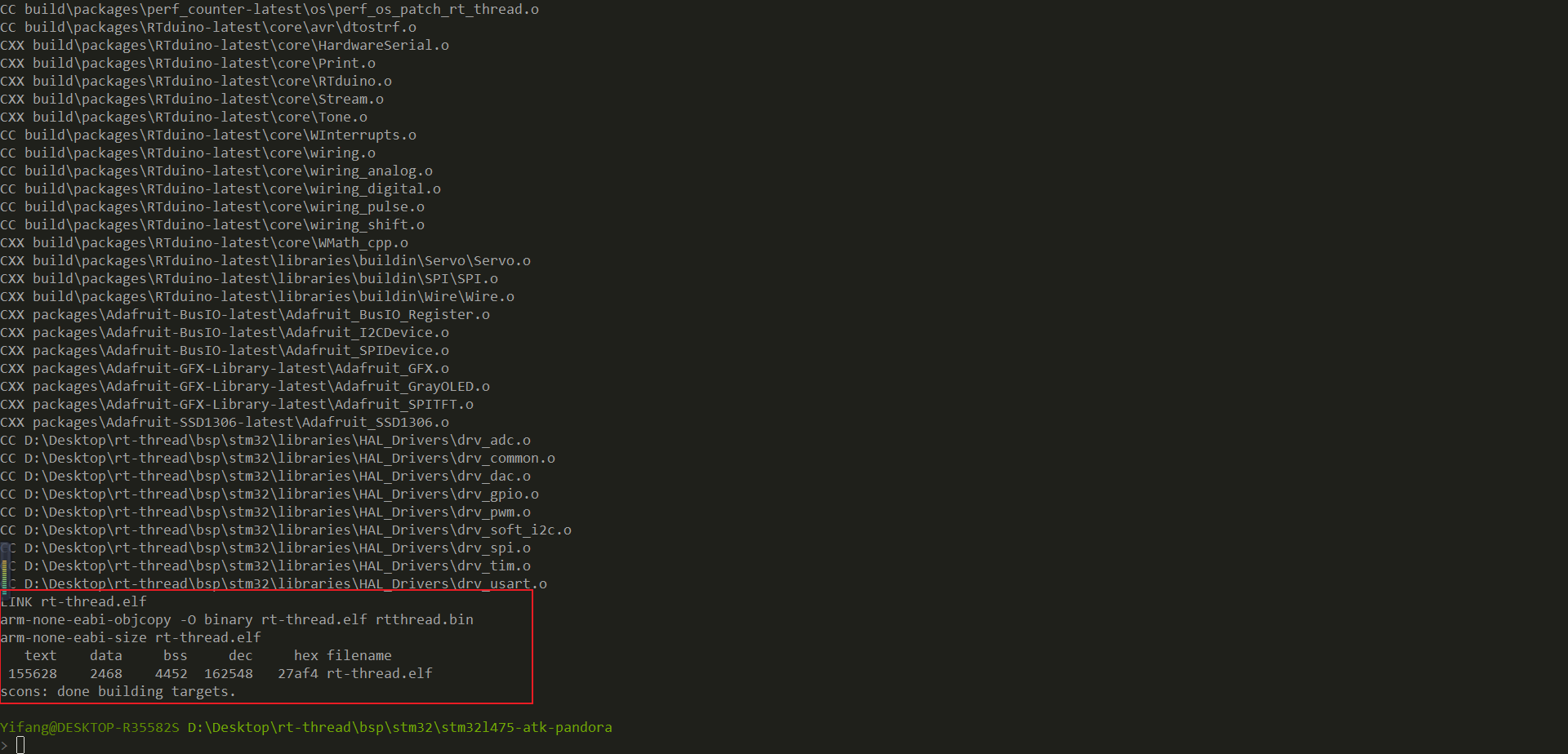 编译完成后会生成`rt-thread.elf`文件。 ## 程序烧录 打开`STM32CubeProgrammer`,选择我们刚刚生成的`rt-thread.elf`文件,点击烧录,重启开发板,即可看到演示效果
0
条评论
默认排序
按发布时间排序
登录
注册新账号
关于作者
加缪
这家伙很懒,什么也没写!
文章
15
回答
47
被采纳
5
关注TA
发私信
相关文章
1
BBB的SPI驱动
2
求个SPI上挂两个或多个设备的使用例子
3
SPI设备有个bug
4
spi flash 的fatfs使用一段时间后读写文件出现故障
5
SPI驱动
6
请教rt_spi_configure函数理解
7
SPI FLASH挂载的问题
8
SPI-FLASH 文件系统 SPIFFS
9
求助一个完整的 spi flash 驱动
10
关于同时使用文件系统与SPI FLASH的问题
推荐文章
1
RT-Thread应用项目汇总
2
玩转RT-Thread系列教程
3
国产MCU移植系列教程汇总,欢迎查看!
4
机器人操作系统 (ROS2) 和 RT-Thread 通信
5
五分钟玩转RT-Thread新社区
6
【技术三千问】之《玩转ART-Pi》,看这篇就够了!干货汇总
7
关于STM32H7开发板上使用SDIO接口驱动SD卡挂载文件系统的问题总结
8
STM32的“GPU”——DMA2D实例详解
9
RT-Thread隐藏的宝藏之completion
10
【ART-PI】RT-Thread 开启RTC 与 Alarm组件
热门标签
RT-Thread Studio
串口
Env
LWIP
SPI
AT
Bootloader
Hardfault
CAN总线
FinSH
ART-Pi
DMA
USB
文件系统
RT-Thread
SCons
RT-Thread Nano
线程
MQTT
STM32
FAL
RTC
rt-smart
I2C_IIC
cubemx
UART
ESP8266
WIZnet_W5500
ota在线升级
BSP
PWM
flash
packages_软件包
freemodbus
潘多拉开发板_Pandora
ADC
GD32
定时器
编译报错
flashDB
keil_MDK
socket
中断
rt_mq_消息队列_msg_queue
Debug
ulog
SFUD
msh
C++_cpp
at_device
本月问答贡献
出出啊
1524
个答案
343
次被采纳
小小李sunny
1444
个答案
290
次被采纳
张世争
821
个答案
179
次被采纳
crystal266
555
个答案
162
次被采纳
whj467467222
1222
个答案
149
次被采纳
本月文章贡献
Pai同学
8
篇文章
10
次点赞
RTT_逍遥
2
篇文章
10
次点赞
Rick98
2
篇文章
9
次点赞
加缪
1
篇文章
2
次点赞
河南理工大学恁带劲儿
1
篇文章
2
次点赞
回到
顶部
发布
问题
投诉
建议
回到
底部


